slurry wall

Process Description of a slurry Wall made by Stein HT

[according to DIN EN 1538]

Fields of Application

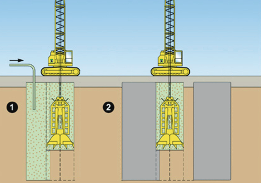
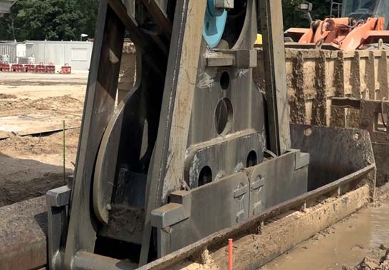
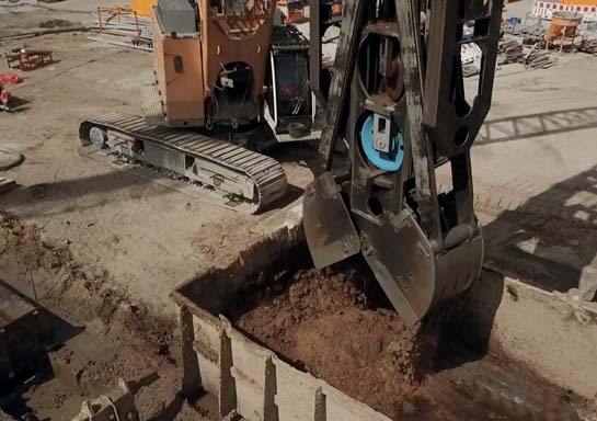
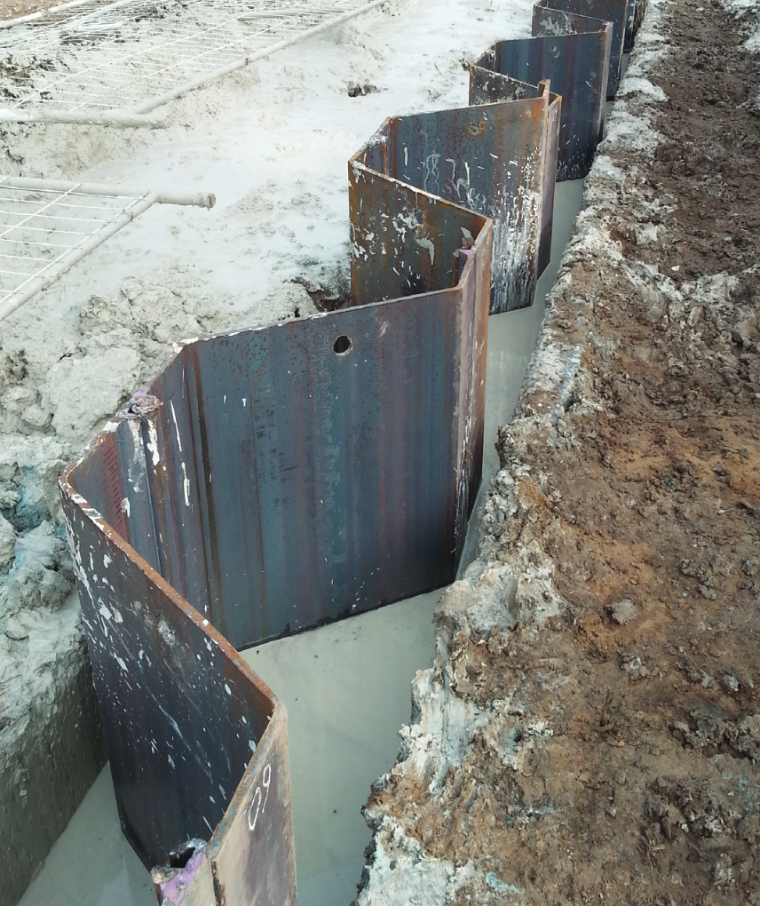
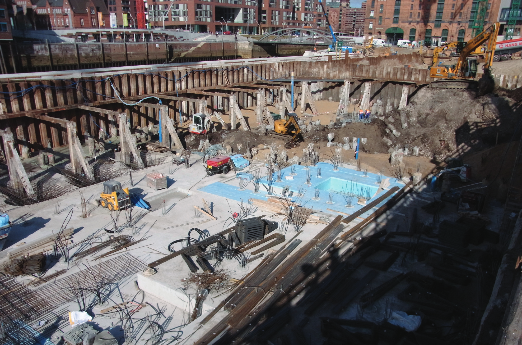
A slurry wall is a vertically executed bentonite-cement wall. It is excavated by means of supporting suspension and has a sealing effect. Both, as a temporary and as a permanent structure, it can also assume structural functions, when combined with sheet piles, girders, or precast units. Wall thicknesses typically range from 600 mm to 1500 mm and depths of max. 40 m are usual, although thicknesses of max. 2000 mm and considerably deeper walls are feasible.


A slurry wall is usually (but not exclusively) used for the following structures:

  • Enclosure/stabilisation of building pits
  • Pipe jacking shafts/entrance blocks
  • Sealing blocks
  • Sluices (as sheet-pile wall)
  • Landfill enclosures
  • Transverse bulkhead for partitioning of building pits

The advantages of a slurry wall in comparison to other foundation processes are as follows:

  • Low-noise and low-vibration construction
  • Low deformation
  • Shorter construction period as against e.g., bored pile walls
  • Sealing effect

Construction of a slurry wall

Site set-up
Pic.1 -Sketch of a site set-up

Pic.1 -Sketch of a site set-up

Site set-up constitutes the start of the building measure. The equipment to be supplied shall be selected in a way that the slurry wall to be built can be implemented in a technically perfect manner and according to the specified schedule. The site equipment area is usually situated within the building plot or directly adjacent to it. Its surface ranges from 200 m² to 300 m².


The site equipment of Stein HT is typically made up as follows:

  • 1 hydraulic crawler crane Liebherr HS8100HD/HS 8130HD or equivalent for cut-off wall excavation (excavator)
  • 1 hydraulic crawler crane Liebherr HS875HD or equivalent for placing sheet piles/girders/precast units (service crane)
  • 1 to 2 diaphragm wall grab/s of a width suited for the Pic.2 -Site Set-up-wall to be built (jaw width corresponding to the arrangement of panels)
  • 1 STEIN diaphragm-wall chisel of suitable width
  • 1 STEIN diaphragm-wall plough
  • 1 STEIN container mixing plant 4.50 m³
  • 1 to 2 silo/s including screw-conveyor for slurry wall powder
  • Quantity of STEIN bentonite storage containers accoding to the size of the open panels (of 100 m³ capacity per set, each)
  • 1 wheeled loader Liebherr 526 or equivalent
  • 1 STEIN intermediate skip
  • Quantity of Mohno bentonite pumps
  • Quantity of Varisco bentonite pumps
  • 1 compressor (electric or diesel)
  • 1 workshop container
  • 1 laboratory container
  • Further accessories like excavator mats, guide wall protection etc.

Abb.2 -Baustelleneinrichtung-

Abb.2 -Baustelleneinrichtung-

Guide wall construction

Pic.4 -Sketch for guide walls

Sketch for guide walls

Gui-wall-elements are availabfe
in length: 5,00m / 4,00m / 3,00m / 2,00m
in height 1,30m / 1,00m

width of diaphragm wall [m]0,600,801,001,201,50
guide-wall width [m]0,6350,8351,0351,2351,535

guide-walls view


Abb.3 - Leitwandbau

Guide wall construction forms part of the further preparation for the slurry wall works as such. These guide walls have the following functions:

  • Position stability in the ground plan
  • Vertical guidance of the diaphragm wall grab
  • Prevention of scouring of the soil, as the slurry wallmaterial

level is always kept within the guide wall. For this purpose, the guide walls will be designed as a double-sided R.C. angular retaining wall of a height of at least 1.00 m. At the latest during excavation of the guide wall trench, the real position of any existing supply and sewage lines will be ascertained. If any pipelines are installed in the area of influence of the slurry wall, they will have to be relocated.

guide-walls topview

Abb.3 - Leitwandbau

On site, a trench will be excavated for construction of the guide wall. In this trench, the slurry wall alignment will be adopted according to the panel plan and marked by means of batter board. Then precast concrete elements will be placed along this alignment. These slabs are max. 5.00 m long and max. 1.30 m high and are provided with a projecting reinforcement in longitudinal direction and a projecting reinforcement for the guide wall base.

The inner slab will be shored up against the outer slab. Then the reinforcement for the guide wall base will be completed and a base of 30 cm will be affixed by concreting.

As a next step, the gaps between the individual slabs will be reinforced, encased and concreted. After removal of formwork, the guide wall trench will be backfilled and compacted. As dimensioning for the clearance between the guide wall sides, an additional trench width of 3.5 cm has proven. Thus, easy handling when immersing the diaphragm-wall grab into the open panel at simultaneous narrow guidance during excavation is given.

Arrangement of panels

Panel-arrangement

After completion of the guide wall, its position will be re-examined by the surveyor and approved by the site management. Afterwards the positions of the panels of the slurry wall are marked on the guide wall by means of steel nails or signal colour. Finally, every panel is marked with the corresponding panel number.

Principle
Suspension-supported excavation is carried out by means of cable-guided, mechanical STEIN diaphragm-wall grabs.

For technical reasons, the panels are classified into:

  • Primary panels
  • Secondary panels

The primary panels are manufactured first. As neighbouring secondary panels, lengths ranging from one cut width to a complete primary panel may occur depending on the soil mechanics conditions. The secondary panels will not be excavated before the neighbouring primary Excavationpanels have developed sufficient strength. In contrast to the diaphragm wall, no joint system is used here. The secondary panels excavated later on virtually act as “joints” between the primary panels.

Construction of a slurry wall

Construction of a slurry wall

Excavation
Excavation

The process is the same for every panel of the slurry wall. First the diaphragm wall grab is set up for the panel. To ensure a continuous slurry wall, an overlap of usually 20 to 30 cm in relation to the previous cut is surveyed for every new excavation cut. According to the excavation progress, the excavated soil is continuously replaced by the slurry wall material.

Excavation

In this context, attention is paid to the fact that the suspension level must not fall below 30 cm, measured at the upper edge of the guide wall. The excavated soil is temporarily stored on the site behind the excavator for subsequent disposal or thrown into an intermediate skip and loaded on trucks by means of wheeled loaders.

At regular intervals, the slurry wall depth is measured by means of a plumb. At the same time, the excavated soil layers are recorded. The final depth of the panel of the slurry wall is approved by the site management. Together with other information on the dimensions of the panel, slurry wall material and any sheet piles placed, these conditions are recorded in a slurry wall report per panel.

Excavation

After reaching the final depth and in case of work interruptions, the open panel will be covered. The employment of staff, use of equipment, slurry wall development and peculiarities will be documented in complementary daily reports.

Excavation

Proof of verticality
The verticality measurement of the panel is qualitatively carried out by means of the grab cables. The excavator operator can identify any deviations of the grab along the slurry wall alignment by means of two alignment bars in the grab area. His assistant at the trench observes any deviations of the diaphragm wall grab in transversal direction to the slurry wall alignment. As long as the grab is visible, both orient themselves by the grab frame. During the progress of excavation, the grab is no longer visible, and both orient themselves by the hoisting cable of the grab. In case of a deviation of the grab, the hoisting cable accordingly moves away from the middle of the guide wall. Moreover, the verticality of the panel of the slurry wall is quantitatively measured by means of an inclinometer made by Jean Lutz and via the Liebherr measuring system PDR2. The data measured by the inclinometer mounted in the grab are transmitted by radio to the driver cabin of the excavator for every excavation stage. The excavator operator can thus track deviations of the diaphragm wall grab in the x- and y-axis, as well as the twisting. The results of the measurement of the respective panel are transmitted by the PDR2 system to a Liebherr server, where they can be retrieved. Illustration are made via diagrams with the respective deviations depending on the depth. In case a too large deviation from the vertical is ascertained, the deviation will be removed by means of the diaphragm wall plough. It is hence guaranteed that the deviation of 1 % as defined in DIN EN 1538 is not exceeded.
Pic.8 -Excerpt from the proof of verticality

Excerpt from the proof of verticality

Installation of sheet piles/girders/precast units
Pic.9 -Sheet pile installation

Pic.9 -Sheet pile installation

As the slurry wall material continuously hardens, the fixtures should be installed as soon as possible. These installations are supplied to the site according to the reinforcement drawings. The local site management shall be responsible for acceptance of the installations. For picking up the fixtures, the service crane is used. The service crane picks up the fixture at the head end. Then the
service crane pulls the head of the fixture towards the tip of the boom and either temporarily stores it in a suitable place on the site or directly installs it into the panel. In case of larger panel depths, it is usual to split the fixtures lengthwise. Then they consist of a top and bottom part and/or of a top, centre, and bottom part. One part, each, is lowered and supported on the guide wall. Then
the following part is placed and connected in accordance with the static plans. After achievement of the final length, the fixture is let down to the required target position. Then the height and length of the fixture is checked and corrected if need be.

Quality management

For quality assurance, a person on the site will be entrusted with the execution of the following inspections and their documentation in slurry wall reports and daily reports,

  • Trench depth
  • Verticality of the trench
  • Suspension monitoring
Site clearance

After excavation of the last panel (with installations, as appropriate), the slurry wall works as such are completed. The facilities will be dismantled, and all equipment removed from the site. As soon as the site is cleared, excavation of the building pit can start. During this excavation, the guide walls will also be removed.

Consent Management Platform by Real Cookie Banner